Procedural Mesh in RealityKit
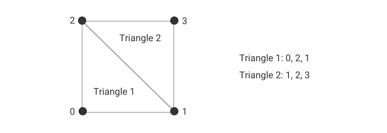
Sometimes you need to create a mesh at runtime. You might want to allow the user to create custom geometry or you're creating geometry based on information you only have at runtime like the size of the detected plane. Meshes consist of triangles so you need to provide the points that make up the triangles which are called vertices. You first provide the positions of the vertices and then the indices of those positions that make up each triangle. The order matters. You specify the triangle vertices in a clockwise order. RealityKit uses the vertices to work out the normal of the triangle i.e. which way the triangle is facing. If the triangle is facing away from the user it won't render.
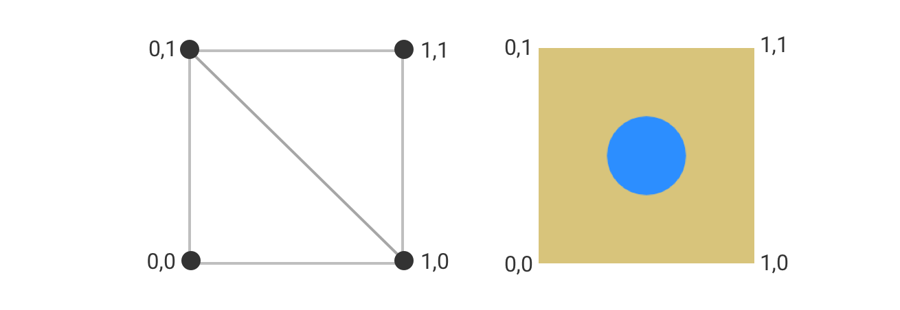
At each vertex you specify a texture coordinate which consists of u,v coordinates that go from 0,0 to 1,1. This is the location in the image that maps to the vertex.
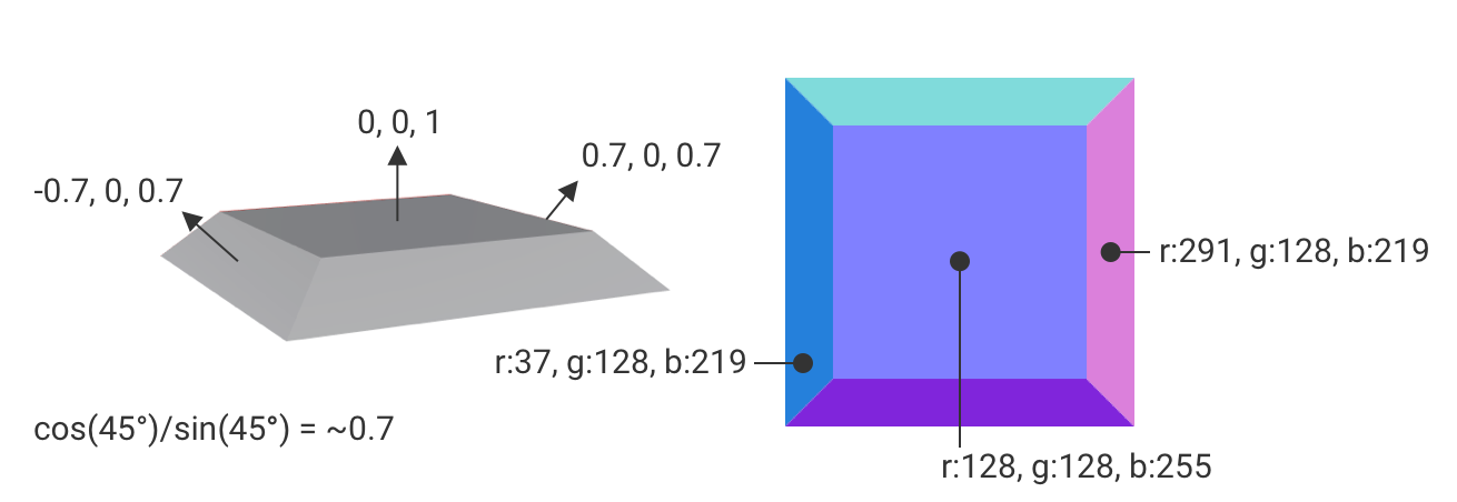
Normals, tangents and bitangents are calculated automatically for you though you can specify them yourself if you want. They make up a local coordinate system on the surface at the vertex called the tangent space. This is used to transform vectors in the normal map to world space. Normal maps provide surface detail to the typical low poly meshes used in real-time rendering. They encode the normal of the surface at each pixel using RGB. A vector in each axis is mapped from -1..1 to 0..255.
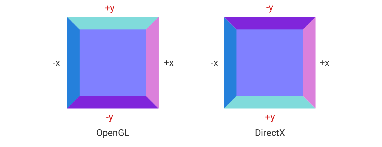
There are two ways to encode normal maps. OpenGL has the Y axis going from bottom to top i.e. Y vectors pointing down will be negative, while Y vectors pointing up will be positive. DirectX is the opposite. RealityKit and Unity are in the OpenGL camp, while Unreal and Substance Designer are in the DirectX camp. If you are exporting textures from Substance Designer you will need to pipe the normal bitmap data through a normal node to invert the green channel if you are exporting the textures to RealityKit.
Below is code to create a procedural plane mesh where you can specify the number of cells along each direction. Positions, textureCoordinates and triangle indices are populated for each cell in the grid.
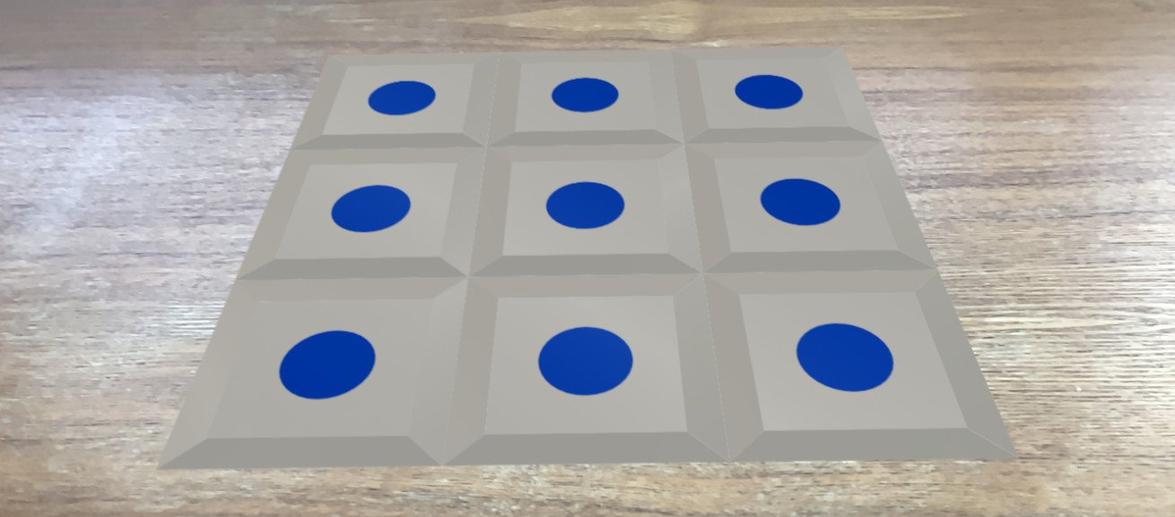
private func buildMesh(numCells: simd_int2, cellSize: Float) -> ModelEntity {
    var positions: [simd_float3] = []
    var textureCoordinates: [simd_float2] = []
    var triangleIndices: [UInt32] = []

    let size: simd_float2 = [Float(numCells.x) * cellSize, Float(numCells.y) * cellSize]
    // Offset is used to make the origin in the center
    let offset: simd_float2 = [size.x / 2, size.y / 2]
    var i: UInt32 = 0

    for row in 0..<numCells.y {
        for col in 0..<numCells.x {
            let x = (Float(col) * cellSize) - offset.x
            let z = (Float(row) * cellSize) - offset.y

            positions.append([x, 0, z])
            positions.append([x + cellSize, 0, z])
            positions.append([x, 0, z + cellSize])
            positions.append([x + cellSize, 0, z + cellSize])

            textureCoordinates.append([0.0, 0.0])
            textureCoordinates.append([1.0, 0.0])
            textureCoordinates.append([0.0, 1.0])
            textureCoordinates.append([1.0, 1.0])

            // Triangle 1
            triangleIndices.append(i)
            triangleIndices.append(i + 2)
            triangleIndices.append(i + 1)

            // Triangle 2
            triangleIndices.append(i + 1)
            triangleIndices.append(i + 2)
            triangleIndices.append(i + 3)

            i += 4
        }
    }

    var descriptor = MeshDescriptor(name: "proceduralMesh")
    descriptor.positions = MeshBuffer(positions)
    descriptor.primitives = .triangles(triangleIndices)
    descriptor.textureCoordinates = MeshBuffer(textureCoordinates)

    var material = PhysicallyBasedMaterial()
    material.baseColor = .init(tint: .white, texture: .init(try! .load(named: "base_color")))
    material.normal = .init(texture: .init(try! .load(named: "normal")))
    let mesh = try! MeshResource.generate(from: [descriptor])

    return ModelEntity(mesh: mesh, materials: [material])
}
Below you can see the tangent space axes visualised. The black spheres are the vertices, the normal axis is represented by the blue sphere, the tangent axis by the red sphere and the bitangent axis by the green sphere.
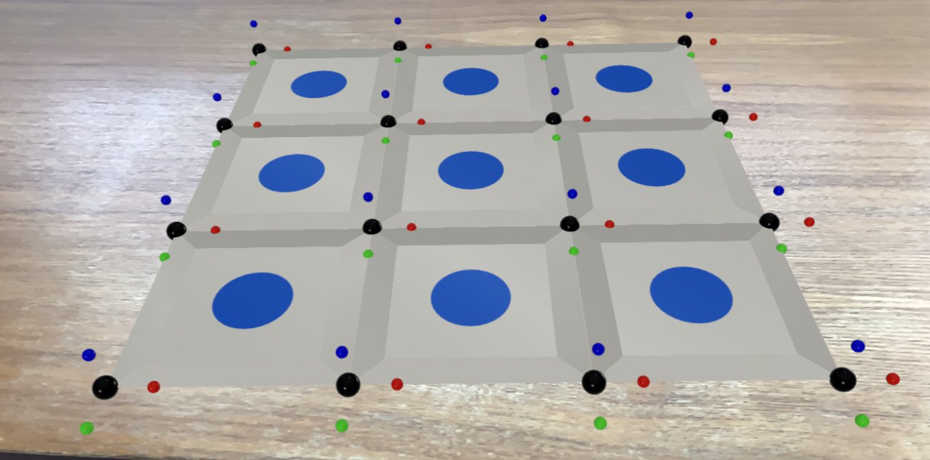
private func showTangentCoordinateSystems(modelEntity: ModelEntity, parent: Entity) {
    let axisLength: Float = 0.02

    for model in modelEntity.model!.mesh.contents.models {
        for part in model.parts {
            var positions: [simd_float3] = []

            for position in part.positions {
                parent.addChild(buildSphere(position: position, radius: 0.005, color: .black))
                positions.append(position)
            }

            for (i, tangent) in part.tangents!.enumerated() {
                parent.addChild(buildSphere(position: positions[i] + (axisLength * tangent), radius: 0.0025, color: .red))
            }

            for (i, bitangent) in part.bitangents!.enumerated() {
                parent.addChild(buildSphere(position: positions[i] + (axisLength * bitangent), radius: 0.0025, color: .green))
            }

            for (i, normal) in part.normals!.enumerated() {
                parent.addChild(buildSphere(position: positions[i] + (axisLength * normal), radius: 0.0025, color: .blue))
            }
        }
    }
}

private func buildSphere(position: simd_float3, radius: Float, color: UIColor) -> ModelEntity {
    let sphereEntity = ModelEntity(mesh: .generateSphere(radius: radius), materials: [SimpleMaterial(color: color, isMetallic: false)])
    sphereEntity.position = position
    return sphereEntity
}
You can download the code from here.